How to cut traces and wire jumpers on Arduino Shield PCB
-
I'm a total hardware engineering noob who's getting into Arduino development. I have an Electric Imp connected to the Arduino via a https://www.sparkfun.com/products/11401, which works great. However, I've added another shield that conflicts with the pins that are used by the Electric Imp for software serial IO. The Imp shield says that I can cut a trace and wire a jumper to use hardware serial on two open ports instead. I've never done this before – can someone give explicit steps as to what I need to do? - http://forums.electricimp.com/discussion/comment/12650#Comment_12650 mentions what is needed, but I don't know how to read a schematic. - Someone has done what I think is the jumper part http://www.instructables.com/id/IMP-ERSONATOR-Electric-Imp-Arduino-Wave-Shiel/step2/Add-Jumper-Wires-to-Imp-Shield/ but no mention of cutting the traces. It's a very similar project to mine.
-
Answer:
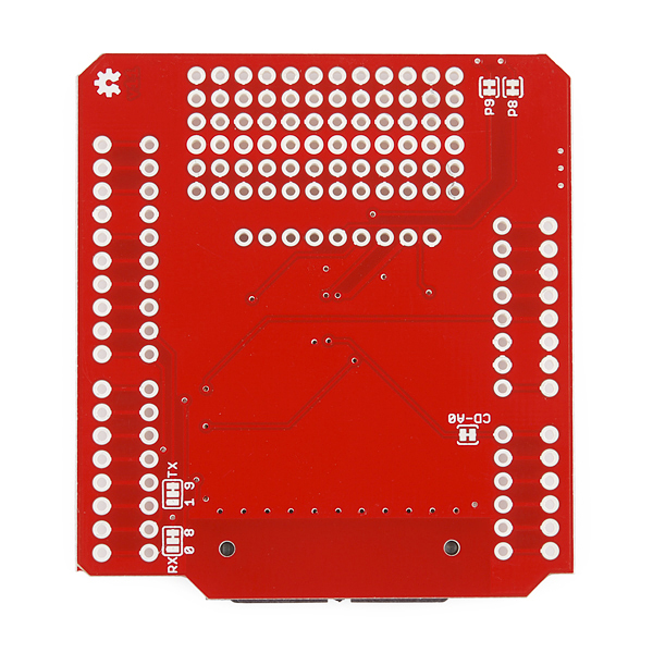
If you don't know how to read a schematic, this is a great way to start learning! http://dlnmh9ip6v2uc.cloudfront.net/datasheets/Dev/Arduino/Shields/electric-imp-shield-v11.pdf; SJ1 and SJ2, mentioned in the thread you linked, are the symbols in the top-right. They have similar symbols to all the other components, but they actually just correspond to the sections labeled RX and TX on the underside of the board, in the bottom-left of https://dlnmh9ip6v2uc.cloudfront.net//assets/parts/7/1/8/4/11401-03.jpg The narrow trace connecting two of the pads in the RX section connects the Imp to Arduino pin 8, which is apparently the RX pin for the Arduino's software-emulated serial port. (So it's labeled RX, even though the Imp itself is transmitting on that pin.) The third pad is connected to Arduino pin 0 and nothing else. It sounds like you want to switch the serial connection from pins 8/9 to pins 0/1, right? Then all you need to do is: 1. Cut the two traces with a knife -- an X-Acto or similar craft knife, or even a pocket knife, should work fine. Depending on the thickness of the trace and soldermask, you might need to sort of scratch it out. 2. Check with a multimeter that there's no continuity between the pads, to make sure you've cut all the way through. 3. Put a blob of solder (aka "solder bridge") between the center "RX" pad and the pin-0 pad. Don't go overboard; use just enough solder to nicely cover both pads. Repeat for "TX" and pin-1. 4. Test continuity again between Arduino pins 0/1 and Imp pins P5/P7 to make sure the soldered connection is good. If you have problems making the solder bridge, you can always do what the person in your last link did and use wires instead, but this way is a little neater. Good luck!
krunk at Ask.Metafilter.Com Visit the source
Other answers
(balls! teraflop beat me to an answer I was composing. Yeah, what they said ...) Note that connecting 0 & 1 to a shield will mean that you'll have to take the shield off to program the Arduino underneath. Unos only have one hardware serial port, unfortunately.
scruss
Yes, this is exactly what I needed! Thanks to both of you for the quick responses. The shield is now working perfectly, although as scruss mentioned I have to remove the shield to program the Arduino. More annoyingly, I can no longer use the serial monitor for debugging – is there a good way of getting around this? My project didn't seem to be working at first, but after reprogramming it a few times it sprung to life, which seems to be the case with Arduino more often than not. Thanks again!
krunk
If you want to get your hardware serial back, you could move the Electric Imp software serial to different, open pins. This would be a manual wiring job, though, and assumes your other shield doesn't eat up the pins you'd need.
Standard Orange
Yeah, it would be nice if there was an easy way to select which ports to use. I guess that's the downside to using shields. I suppose if I always had the Imp as the topmost shield I could solder wires from Imp pins P5/P7 and attach them to the stackable header on the Arduino pins that I need? Would I have to reverse the trace that I cut?
krunk
Related Q & A:
- How To Cut Men Hair?Best solution by Yahoo! Answers
- How To Cut Hair?Best solution by Yahoo! Answers
- How To Cut Video?Best solution by Yahoo! Answers
- How to program a CAN-BUS arduino shield to control car windows?Best solution by Arduino
- How do i need to wire my 12inch rockford fosgate punches correctly coming out of the amp and what size wiring?Best solution by Yahoo! Answers
Just Added Q & A:
- How many active mobile subscribers are there in China?Best solution by Quora
- How to find the right vacation?Best solution by bookit.com
- How To Make Your Own Primer?Best solution by thekrazycouponlady.com
- How do you get the domain & range?Best solution by ChaCha
- How do you open pop up blockers?Best solution by Yahoo! Answers
For every problem there is a solution! Proved by Solucija.
-
Got an issue and looking for advice?

-
Ask Solucija to search every corner of the Web for help.

-
Get workable solutions and helpful tips in a moment.

Just ask Solucija about an issue you face and immediately get a list of ready solutions, answers and tips from other Internet users. We always provide the most suitable and complete answer to your question at the top, along with a few good alternatives below.